## In short
Electrical standards compliance often fails not because engineers lack knowledge, but because tools fail to enforce it during the workflow. When validation happens only at the end, inconsistent data spreads and fixes become expensive. Custom electrical design software shifts validation earlier, prevents unsupported configurations automatically, and reduces costly rework.
---
## Electrical design software should enforce standards
Whether your project references IEC, IEEE, ANSI or NEC, the break point is usually the same: between what the standard expects and what the software actually checks.
That is the hidden cost of standard software. It creates work that looks finished, but still depends on senior knowledge, late review and manual approval. In practice, that means electrical standards compliance is delayed until the end of the workflow—when fixes are the most expensive.
A change in one part of the documentation often forces manual updates in several others. Validation still happens at the end, by a human. Even an 80% correct schematic is not real progress if finding the missing 20% takes more time than redrawing it from scratch—what Synergy Codes' internal data shows from working with clients.
## Where electrical standards compliance breaks inside a standard CAD workflow
The breakdown usually starts with fragmentation.
The schematic lives in one tool. The component library sits somewhere else. Rules live in documents, spreadsheets or senior engineers' heads. Exports move through PDF. Change tracking happens in email, comments or a separate tracker. Sound familiar?
But sometimes the problem is even more fundamental: there are no rules yet. Device lists, equipment configurations, and naming conventions are not standardized—each engineer documents them differently. This creates inconsistency that spreads before standards can even be enforced. The first step is often establishing what those standards should be, then building them into the tool.
The more disconnected the workflow becomes, the harder it gets to maintain consistency across the system.
| Where the workflow lives | What usually goes wrong |
|---|---|
| CAD or other electrical diagram software | Engineers can draw valid-looking diagrams that still break project-specific rules. |
| Separate component databases | Symbols, ports, and properties drift away from real devices or approved variants. |
| PDF exports and manual reviews | Errors are found late, after the wrong data has already spread. |
| Version comments in email, spreadsheets, and PDFs | Change history becomes hard to reconstruct and easy to misread. |
This is also where electrical CAD limitations become obvious. Traditional tools are good at drawing. However, they are much weaker at enforcing client-specific logic, custom symbol systems, device-specific rules or process-specific approvals. Teams often patch those gaps with macros, plug-ins, checklists, and experience. That may work for a while, but it does not scale.
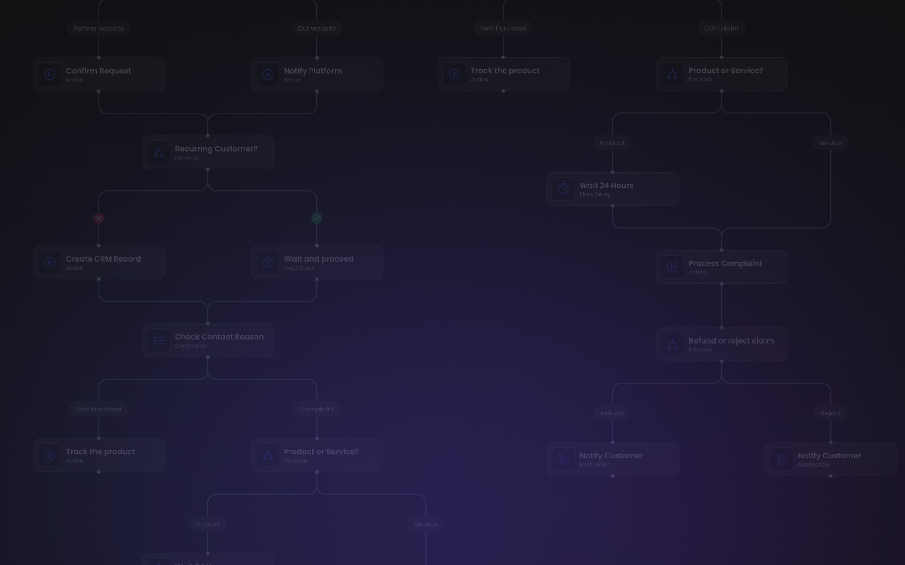
One engineering interview used a simple example: users needed to build electrical schematics from a palette of real devices, not generic shapes, with front-end and back-end validation working together. Every move had to be checked immediately, because waiting until the final review would allow unsupported designs to spread too far. That is not a documentation issue—it is a workflow enforcement issue.
## Why electrical schematics automation fails when the rules stay outside the system
A lot of teams already attempt electrical schematics automation. The problem is that the automation often stops at layout, drawing speed or template reuse. It does not reach the real source of compliance risk—rule enforcement.
If the rules stay outside the system, the tool can only automate geometry, not decisions. This does not show the actual condition of the electrical installation being built, but only its static preview. Engineers still end up relying on manual review for tasks that should be handled by rule-based validation electrical workflows.
Engineers have to ask themselves questions while working:
- Does this component belong here?
- Can these two elements connect?
- Is this symbol allowed for this client?
- Does this version still match the latest specification?
If the software cannot answer those questions in real time, the team has to answer them by trial and error.
| What teams expect from tools | What standard tools often deliver |
|---|---|
| Compliance-aware workflow | Drawing-first workflow |
| Real-time validation | End-stage review |
| Approved symbols and components | Generic libraries |
| Traceable change history | Partial or manual tracking |
This is why many companies start looking beyond off-the-shelf and generic electrical diagram software. They do not need another prettier editor. They need software built around their process, their rules, and their approval logic.
That is also where a custom approach starts to make sense—especially when standards pressure is high, specifications change often and manual review has quietly become the only thing holding the workflow together.
---
## Well-designed electrical design software does things differently
Good electrical design software does not just help engineers draw faster. It changes where control happens in the workflow.
Instead of waiting for someone to review a finished schematic, the system starts enforcing project logic during editing. Instead of relying on generic symbol libraries, it works with the client's actual devices and constraints. Instead of treating the diagram as a static piece of data, it can connect it to live system behavior, access rules and backend logic.
That is where electrical schematics automation becomes useful in a meaningful way—not as design speed, but as process control.
### Real-time, two-way validation catches errors before they spread
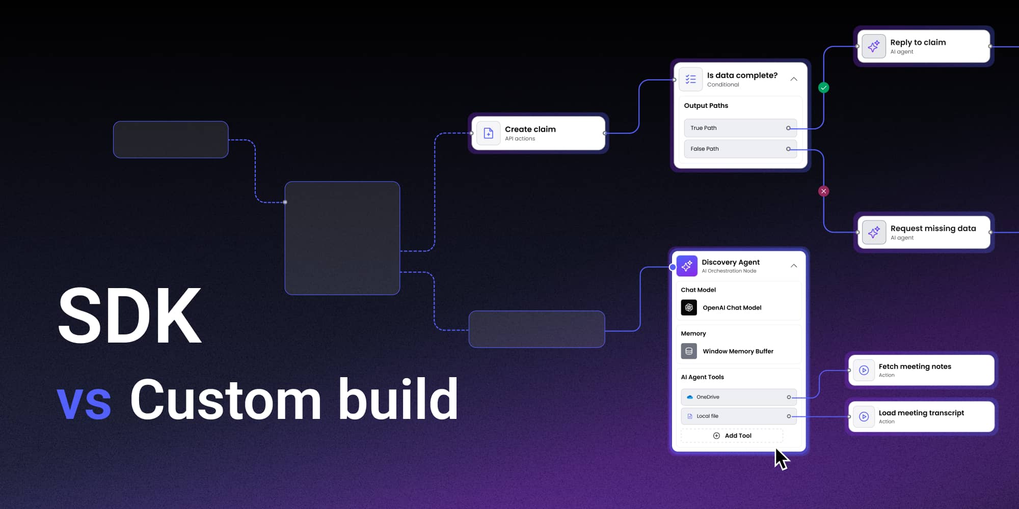
A stronger model goes beyond real-time validation in the editor. It keeps the editor connected to the client's backend logic, so engineers can only create what the simulator or downstream system actually supports.
That changes electrical design software in a practical way. Instead of relying on someone to catch an issue later, the tool enforces the client's business rules during the design process. Available components, properties and allowed connections can be pulled dynamically from the backend, where the real product logic already lives.
The result is simple: you cannot design something the system does not support. Not because a reviewer spots it later, but because the software does not allow that invalid state to exist. That is what mature electrical schematics automation looks like. The editor stops being just a drawing surface and becomes a control layer tied to the simulator, device model or business logic behind the product.
### Dynamic backend rules turn design into a control layer
A lot of engineering teams still work in editors where rules are effectively hardcoded or handled outside the system. That becomes fragile as soon as components, variants, or specifications start changing.
Custom electrical design software works differently. It can pull business rules dynamically from the backend, so the logic in the editor stays aligned with the actual logic of the client's system. The result is much stronger than a checklist or a review step.
It means:
- The available elements can change with the source data
- The allowed properties can reflect the actual device model
- Unsupported combinations can be blocked automatically
- Engineers cannot design something the simulator or downstream system does not support
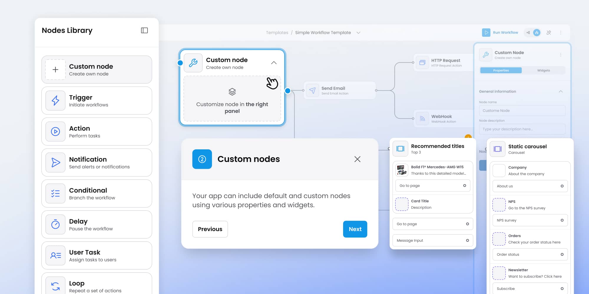
### Component libraries should reflect real devices, not generic shapes
Generic shape libraries are fine for early sketches. They are much less useful in production workflows where the diagram has to reflect real devices, real properties and real constraints.
This also matters for long-term maintainability. If the source system changes, the library can evolve with it. That is far more resilient than manually updating symbols and labels in multiple places. It is also one of the clearest ways to move beyond common electrical CAD limitations, where the visual layer is separated from the actual logic of the system.
### Real-time monitoring turns live device data into immediate alerts
In some environments, the diagram is not just a place to design a system—it is where engineers need to see live signals from real devices and react fast when something changes.
In Synergy Codes' projects, diagram elements can be connected to real-time device data and rule-based logic. When a live parameter changes, the status on the diagram updates immediately. If a threshold is exceeded or a configured condition is met, the system can trigger an alert right away.
That changes the role of electrical design software in a fundamental way. The diagram stops being static documentation and becomes a live operational surface tied to actual system behavior. For teams working with complex infrastructure, this means electrical schematics automation can support much more than editing. It can help monitor real devices, surface issues earlier and apply configured rules consistently—without waiting for someone to notice a problem manually.
### User modes protect data integrity
Not every user should have the same level of control over a diagram. In some cases, one person needs to edit while another only needs to review, inspect or export.
That may sound like a small feature, but it has real process value. It protects data integrity, reduces accidental changes and makes it easier to separate authoring from review. It also helps when some users are no-code or low-code users—they can still work with the tool in the right mode, without getting access to actions that could break the logic or structure of the system.
In environments where multiple stakeholders touch the same system, that kind of structure matters just as much as drawing functionality.
---
## Synergy Codes turns engineering rules into software that enforces them
For teams working under IEC, IEEE, ANSI or NEC requirements, the real challenge is not reading the standard—it is translating those rules into a workflow that works under real project pressure. The knowledge of what those standards mean in practice stays on the client's side, with the engineers who know the domain, devices, and constraints best. The role of the Synergy Codes team is to capture those requirements and translate them into custom electrical design software that enforces them automatically.
Synergy Codes can turn those rules into system behavior—so the workflow itself supports consistency, control, and better engineering outcomes.
## 5 warning signs your electrical design software is working against compliance
Teams rarely replace tools after one failure. The pressure builds slowly: a few more manual checks, a few more exceptions. Then one day, the workflow is still technically running, but nobody trusts it.
That is the point where custom systems stop being a nice-to-have and start looking like risk reduction.
### 1. Specification changes trigger manual fixes
A symbol, property or rule changes, and engineers update multiple places by hand. That is not just slow. It makes electrical standards compliance fragile, because every extra touchpoint increases the risk of drift. The problem grows when tools do not reflect real devices, variants or approved notation, or when compliance software is not properly embedded into daily workflows.
### 2. Review is your only validation layer
If unsupported states are only caught by a senior reviewer, validation happens too late. Teams do not want "mostly correct" schematics, because checking the rest costs too much. This model does not scale with complex diagrams and tight timelines, especially without proper schematic design automation.
### 3. Patchwork tooling
Macros, spreadsheets, side documents and internal rules fill gaps left by software. These disconnected electrical engineering tools keep projects running, but rarely make them resilient.
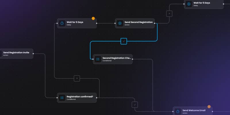
### 4. Version confusion
Teams struggle to track what changed and whether documentation matches actual design logic. When approvals and implementation are disconnected, compliance turns into reconstruction. Without centralized logic or schematic design automation, version control quickly breaks down.
### 5. Errors appear late
If issues show up during testing or commissioning, it is no longer a documentation problem. It is a schedule problem and a sign that validation should have been handled earlier by the system, not by people or fragmented electrical engineering tools.
## A practical checklist for electrical schematics automation readiness
Before you invest in a new tool or a custom build, it helps to ask a better question. Not "Do we need new software?" but "Where does our process break because the tool cannot enforce what we already know?"
Use this quick check:
| Question | If the answer is "yes" |
|---|---|
| Do spec changes force manual edits in several places? | Your workflow is too brittle for scale. |
| Do senior engineers act as the only compliance filter? | Your rules are not encoded in the system. |
| Do you rely on macros or external trackers to keep things aligned? | Your tool stack is fragmented. |
| Do users work with generic symbols instead of approved, real-device libraries? | Your automation is too basic. |
| Are errors discovered late, during implementation or testing? | Validation happens too late. |
If several of these feel familiar, the problem is not your team's discipline. It is the mismatch between your process and your tools. That is also where electrical schematics automation deserves a more serious look.
## When custom electrical design software starts to make sense
Synergy Codes is not here to interpret IEC, IEEE, ANSI or NEC for your team. Your engineers own that expertise. Our role is to turn those requirements into working systems that fit your process instead of fighting it.
That work usually starts with a discovery conversation. The goal is not to jump straight into building. It is to map where standards-related risk enters your workflow, where validation breaks down, what data should drive the editor and which parts of the system would create the biggest payoff first.
---
## FAQ
**Why does electrical standards compliance fail within design even in experienced teams?**
Compliance issues usually do not come from lack of knowledge. They happen when electrical design software does not enforce rules during the workflow, allowing inconsistent data to move forward and errors to appear late.
**What is the biggest limitation of standard software?**
Most tools focus on drawing, not execution. They allow engineers to create valid-looking schematics that may still break project rules, especially when validation happens only at the end instead of in real time.
**How does electrical schematics automation improve compliance?**
Effective electrical schematics automation enforces rules during design—not after. It prevents unsupported configurations, reduces manual checks and ensures consistency across diagrams, components, and data.
**What is a custom schematic editor, and when do you need one?**
A custom schematic editor is tailored to your process, rules and devices. It makes sense when standard tools cannot reflect your workflows, and your team relies on workarounds like macros, spreadsheets or manual validation.
**Why is real-time validation important in electrical workflows?**
Real-time validation shortens the feedback loop. It helps engineers catch issues immediately, before errors spread across files, exports, or systems—reducing rework and improving overall quality.
**Can electrical design software support non-technical users?**
Yes—well-designed systems include role-based access, such as read-only modes. This allows no-code or low-code users to safely interact with the system without risking data integrity.
**When should a company consider custom electrical design software?**
When manual fixes, late validation, version confusion and repeated errors become common, it is a sign that tools no longer support the process. At that point, custom electrical design software can reduce risk and improve consistency.
Kuba Skibiński
Software Developer
Kuba Skibiński is a Software Developer specializing in data visualization, diagram layouts, and AI-driven workflow optimization. Known for challenging conventional thinking, he explores complex problems from fresh perspectives and turns deep technical insight into practical business impact. From transforming early-stage concepts into scalable systems to accelerating engineering workflows from weeks to days, Kuba combines curiosity, innovation, and hands-on expertise to deliver smarter solutions.