How to add workflow execution to a visual workflow editor

You shipped the canvas. Nodes drag, edges route, the properties panel saves. Customers can author beautiful workflows. Now they want to run them – and the visual workflow editor stops being the hard problem. The execution layer takes over, and most teams underestimate what it actually involves.
This is a how-to for the engineering team that has reached that exact point. Not a marketing piece, not a build-vs-buy debate – a working map of what the execution layer has to do, the architectural decisions you face, and the patterns that hold up in production.
The premise is simple: a visual workflow editor produces a graph. To execute that graph, you need a runtime that interprets nodes and edges as steps and transitions, persists state across crashes and restarts, retries failed work, waits on external events without burning resources, and surfaces what is happening to the end user. Every one of those responsibilities maps to a concrete decision. Below is the order of operations for getting them right.
Step 1: Define what your canvas actually exports
Before building any execution, write down – explicitly – what the canvas produces. Most editors export a JSON document with three concerns mixed together: structural metadata (nodes, edges, positions), node configuration (inputs, parameters, code), and execution semantics (which nodes are entry points, which are terminal, what counts as a successful exit).
The execution layer needs the second and third. The first is for re-rendering the canvas. Separating them in the data model – even if the export is one JSON blob – makes everything downstream easier. A typical clean export looks like this:
- Definition → node types, their config, the edges, entry and terminal points. This is the executable.
- Layout → coordinates, viewport, collapsed groups. This is presentation.
- Metadata → version, author, last modified. This is bookkeeping.
The execution engine should read the definition and ignore the rest. This sounds obvious. Teams that skip it end up with engines that crash when a user moves a node to a new coordinate.
Step 2: Pick your execution model
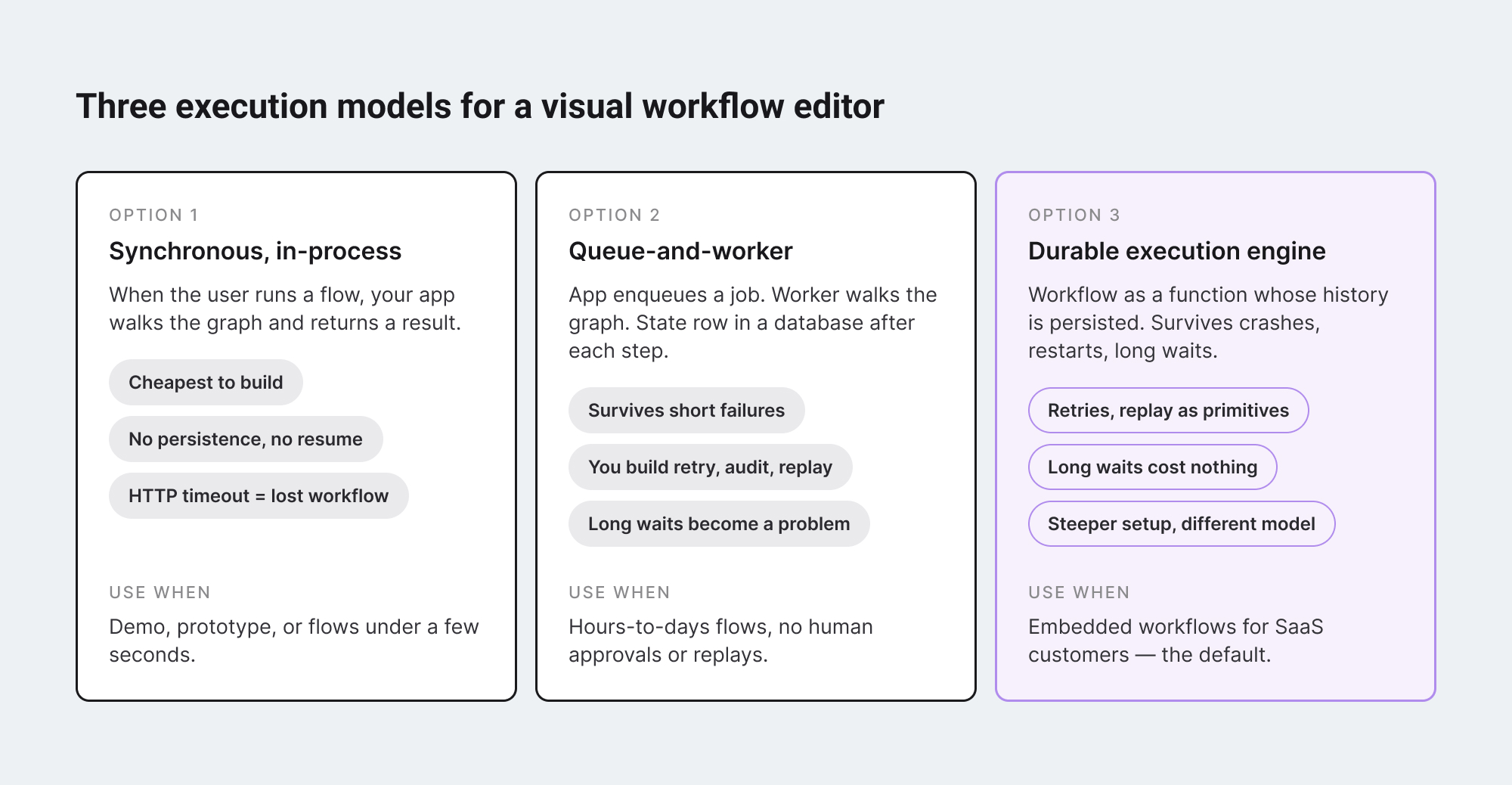
There are three ways to run a graph. Each one has a clean mental model and a different operational cost.
#1 Synchronous, in-process.
When the user clicks Run, your application walks the graph in order, calls each node’s logic, and returns the result. Easy to build, easy to debug, impossible to scale beyond short-running flows. If any step takes longer than your HTTP timeout – or your user closes the browser – the run is gone.
#2 Queue-and-worker.
The application enqueues a job per workflow start. A worker process picks it up, walks the graph, calls each node. State lives in a database row updated after each step. Failures retry by re-reading the row and resuming from the last completed step. This is what most teams build first when they outgrow synchronous execution. It works for hours-to-days flows. It breaks subtly when you need to wait three weeks for an approval, or when a worker crashes mid-step and the next worker doesn’t know which side of the side-effect already happened.
#3 Durable execution engine.
A purpose-built runtime – Temporal, Inngest, Restate – treats every workflow as a function whose entire history is persisted. If a worker dies, another resumes the function from the exact point of failure with no loss of state. The engine handles retries, timeouts, long waits, and replay as primitives. This is the model used by Netflix, Stripe, and Uber for processes that cannot afford to lose their place. It costs more to set up and reasons differently from a normal application – but it is the only model that survives long-running, multi-step, real-world workflows.
For a SaaS product embedding a visual workflow editor, the answer is almost always option three, with the backend swappable. Anything less and you spend a year reinventing pieces of it.
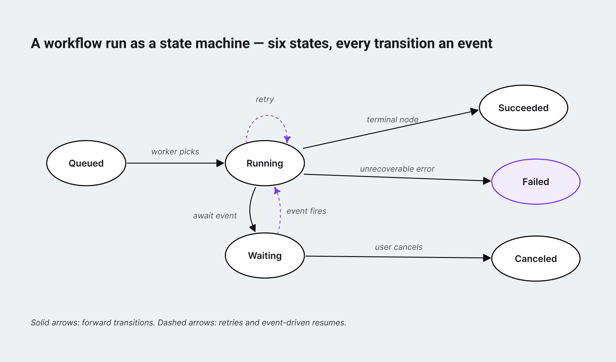
Step 3: Design the run as a state machine
Before any code, draw the state machine of a single workflow run. Most engineers skip this and end up with a state field in their database that grows untracked over time – six values become twelve, twelve become eighteen, and nobody can answer “what does state=23 mean” three quarters later.
A workable minimum is six states: queued, running, waiting, succeeded, failed, canceled. Every transition between them is an event with a timestamp, a reason, and the node it relates to. A run is the ordered log of those events. The current state is the latest event.
This matters for two reasons.
- First, the user interface for showing run status – the part that lives back inside the visual workflow editor – is a direct projection of these states onto canvas nodes. A node is highlighted because the run is in running on that node, faded because it has not been reached, marked red because the run is in failed with that node as the failure point. If your state model is messy, your UI will be messy too.
- Second, every audit and observability question becomes a query over the event log. “What did this run do” is not a special feature – it is the table you already have, ordered by timestamp.
Step 4: Make every node idempotent, or fake it
Once a workflow can retry, every node that does work outside the system has to be safe to call more than once with the same input. This is the part of execution that goes wrong silently. A “send email” node that runs twice during a retry does not throw – it sends the email twice. A “charge customer” node that retries can charge twice. The user sees one workflow run; the customer sees two charges.
Two patterns make this manageable.
- First, every external side-effect is wrapped in an idempotency key derived from the run ID and the node ID. The downstream service uses the key to deduplicate. Stripe, Twilio, and most modern APIs have first-class support for this; the engine just has to thread the key through.
- Second, side-effects are recorded in the engine’s event log before the next step runs. If the worker dies after the side-effect but before the log entry, the engine sees an incomplete step on resume and re-checks the idempotency key with the downstream service instead of blindly retrying.
Durable execution engines bake this in. If you build your own runtime, this is where the most subtle bugs live.
Step 5: Surface live execution back into the visual workflow editor
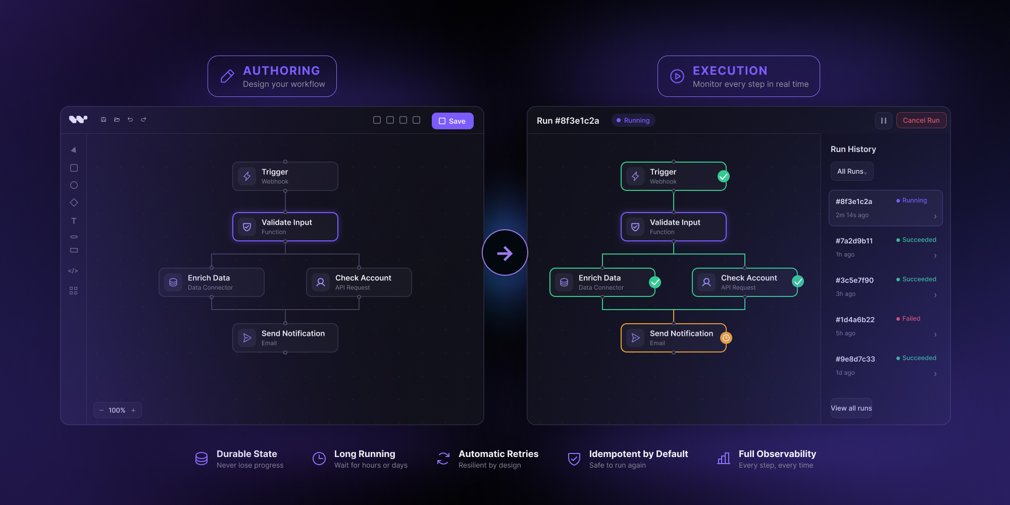
The execution layer is invisible by default. The user authored a graph; now they want to see what is happening to the graph as it runs. This is a feature, not a nice-to-have – it is what changes the product from “draws workflows” to “runs workflows.”
The pattern is straightforward. The engine emits events when run state changes. Those events are pushed to the frontend over a websocket or server-sent event channel. The visual workflow editor subscribes per-run and projects the events onto the canvas: a pulsing border on the currently-running node, a green check on completed nodes, a red mark on failures, a clock icon on nodes waiting for a human or external trigger. The same events drive a side panel that lists run history, inputs, outputs, and any error details.
The canvas component should not own the run state; it should render whatever the subscription tells it. This keeps the editor stateless and reusable for replays of historical runs – the same component renders a live run and a three-week-old archived run, just with different event sources. And the engine’s event schema is part of the public contract of the editor: changing it breaks every downstream consumer, so version it from day one.
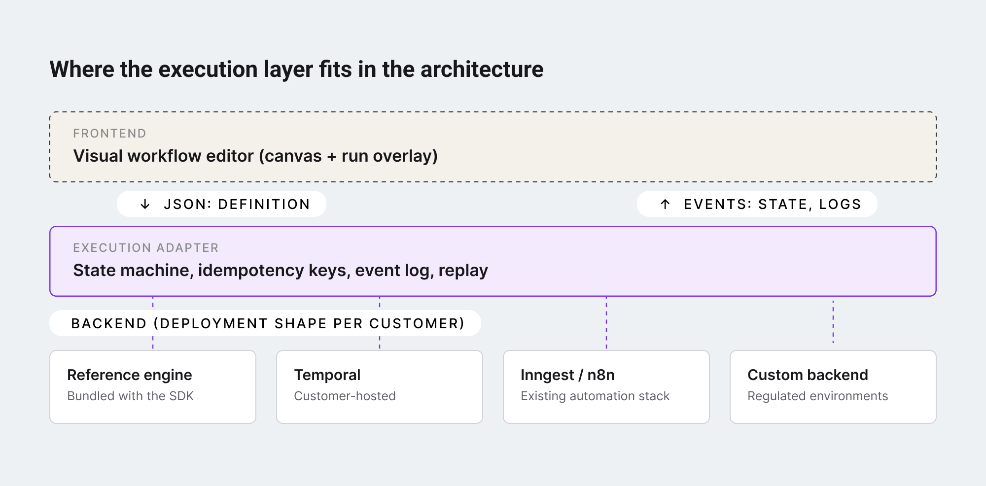
Step 6: Decide where the execution backend actually lives
The last decision is the most architectural. The execution engine has to run somewhere – and a SaaS product embedding a visual workflow editor inherits its customer’s preference about where that somewhere is.
Three deployment shapes show up in practice:
- Hosted by you, the editor vendor. Customers send workflow definitions to your backend; you run them and stream events back. Operationally simplest for the customer, hardest for you – you take on every customer’s reliability, compliance, and scale problem.
- Hosted by the customer, on infrastructure they already run. If the customer has Temporal, Inngest, or a self-hosted automation stack, the visual workflow editor’s execution layer plugs into that. The customer keeps their data plane; the editor stays a thin client. This is the shape that scales for enterprise customers with regulatory or sovereignty constraints.
- Hybrid. The editor ships with a reference engine and a defined adapter contract. Customers without a backend run the reference engine. Customers with one swap it out. The contract – what an “execution backend” has to implement – becomes the most important interface in the system.
Adding execution to a visual workflow editor is six decisions in order:
- clean up your canvas export so the executable part is separable;
- pick an execution model that survives long-running flows;
- design the run as an explicit state machine;
- make every node idempotent or rely on an engine that does it for you;
- surface execution events back into the canvas as a live overlay;
- and decide where the backend deploys, with the adapter contract as your most important interface.
The teams that get this right end up with a workflow product instead of a workflow drawing tool. The teams that defer it end up rebuilding the same execution primitives the durable execution category has already built – and rebuilding them with less rigor, because they were not the team’s main job.
The shortcut, for embedded use cases, is to start with an SDK whose canvas already separates definition from layout, ships with a reference execution engine, and exposes the adapter contract as a first-class API. That is the shape the embeddable workflow editor category has been moving toward – and the shape that lets a small team ship a real workflow product instead of an unfinished one.
Workflow Builder is an embeddable workflow editor SDK by Synergy Codes. Version 2.0 ships with a packaged SDK, a reference execution backend on Temporal, and a swappable engine layer designed to plug into the customer’s existing infrastructure.
Mateusz is a Principal Developer and Solutions Engineer at Synergy Codes, where he works on Workflow Builder. With 7+ years of building interactive diagramming tools and data-heavy web applications, he joins client projects from the earliest conversations, shaping requirements into technical roadmaps and estimates, and stays hands-on through development.